news
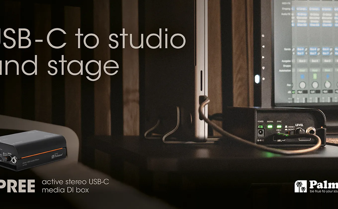
Palmer is expanding its River Series with the spree
an active USB-C stereo DI box for stage, studio and mobile audio setups

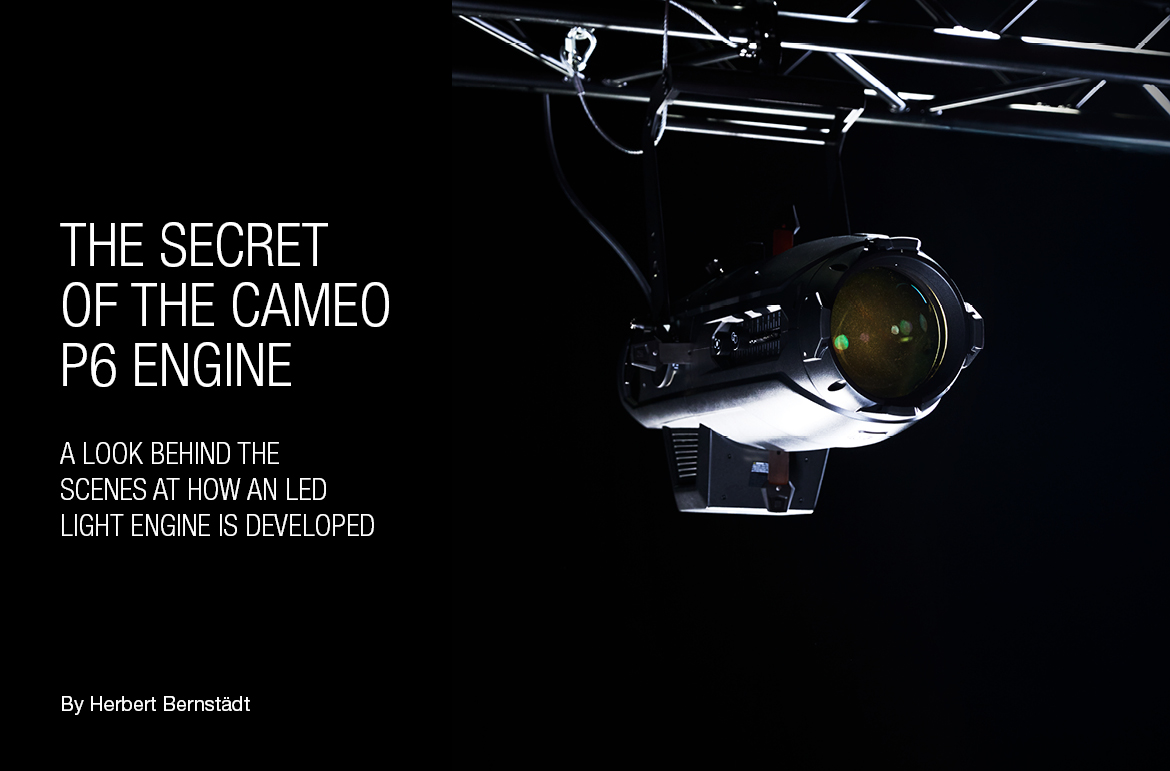
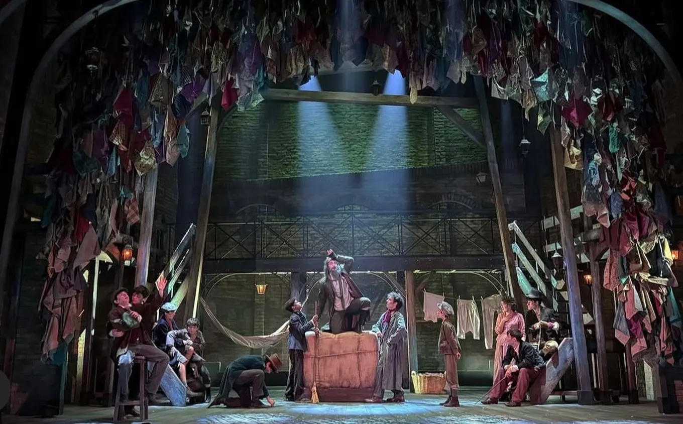
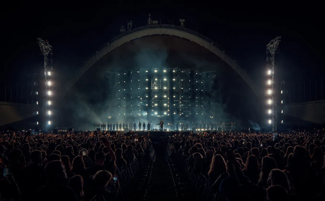
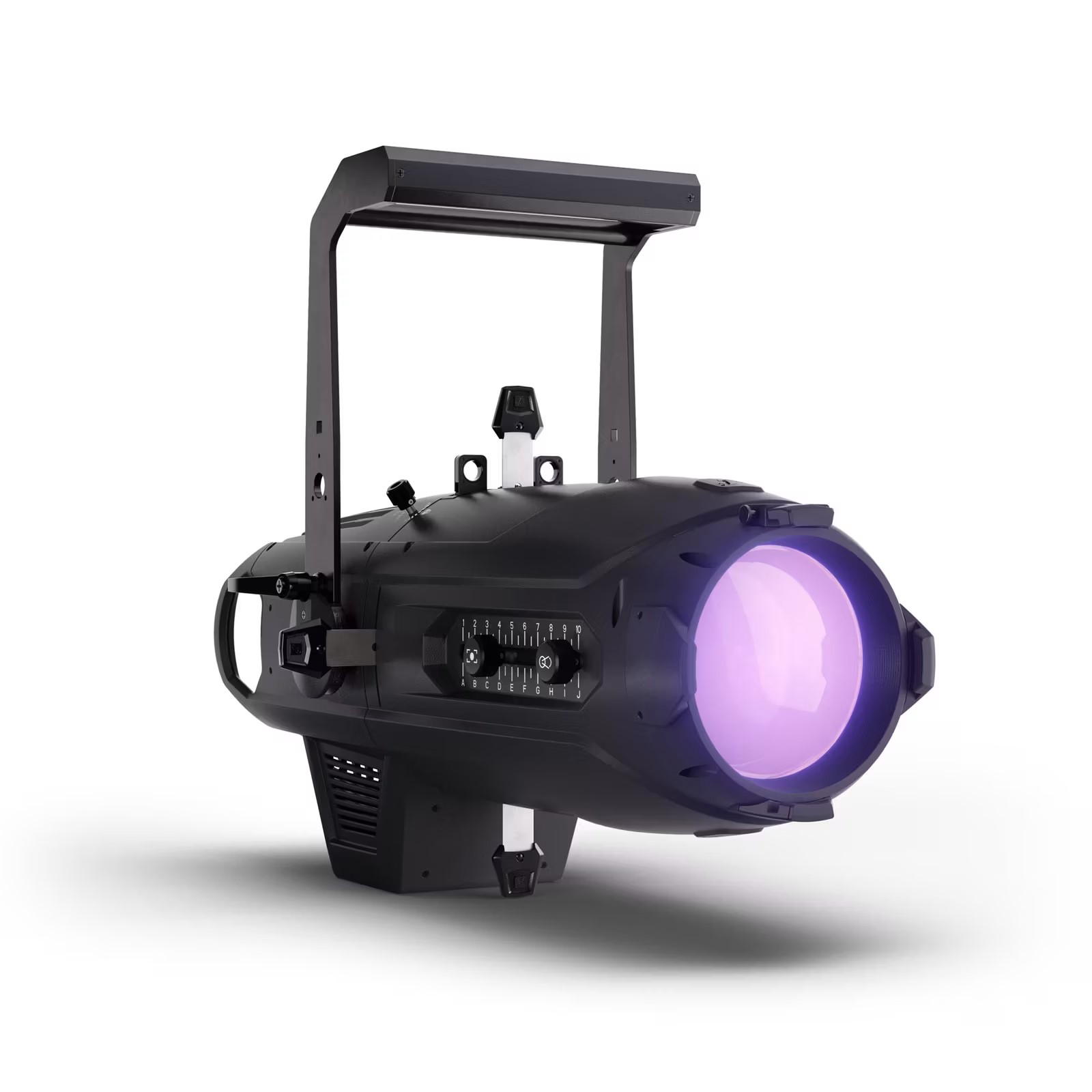
Initially, our only aim was to replace the time-tested 2.5 kW profile spots on the theatre's lighting bridge. This alone placed many demands on the new fixture. Essential requirements included at least the same luminosity and a light quality comparable to that of a halogen lamp. Of course, these were followed by many other requirements – universal usability through a wide zoom range, compact dimensions, and so on. As coloured LED lights are already commonplace in theatres, this fixture had not only to replace halogen lights but also to produce coloured light, thereby avoiding the need to change colour filters and ensuring a consistent look with the other coloured LED lights.
A wide colour palette, high light output and good colour rendering can only be achieved with a multicolour array. Such arrays also make it possible to shift seamlessly from warm white to cool white – mirroring the changes in emotional mood across the dramatic arc. In addition, a multicolour array can tint the white light towards green or magenta, as required for electronic cameras, in order to match a specified white point that is often determined by other light sources.
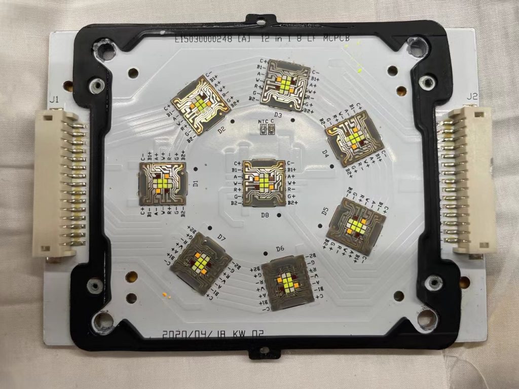
First attempt at a multi-chip arrangement using an existing engine. This solution proved unsuccessful as the light field was too uneven.
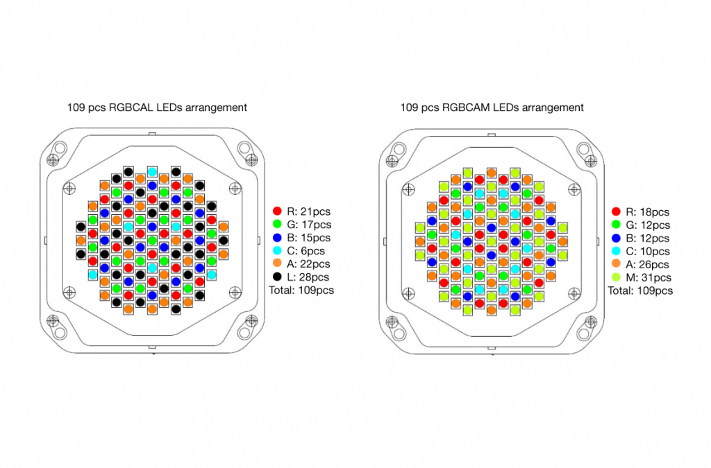
To ensure that the light spectrum is filled as completely as possible – especially in comparison to halogen lamps – the aim is naturally to use as many LED colours as possible. However, this is offset by the fact that the brightness of the individual colours decreases sharply with each additional light colour. A compromise is therefore necessary, which, in our case, we achieved with a six-colour array. The next major challenge is selecting the LEDs themselves. Selecting an LED that will still be available in seven years – if that can even be predicted – naturally points towards brand-new manufacturer LEDs. Quality LEDs are required that are available in a very narrow binning. In addition, the LEDs must be highly efficient and, as a core requirement, provide very high light output. This already shows that the criteria greatly limit the selection of suitable LEDs. Before a particular manufacturer’s LED is decided on, different light colours are tested for their practical effect and how they interact with each other. The focus is always on achieving the highest possible light output while maintaining the best possible colour rendering quality.
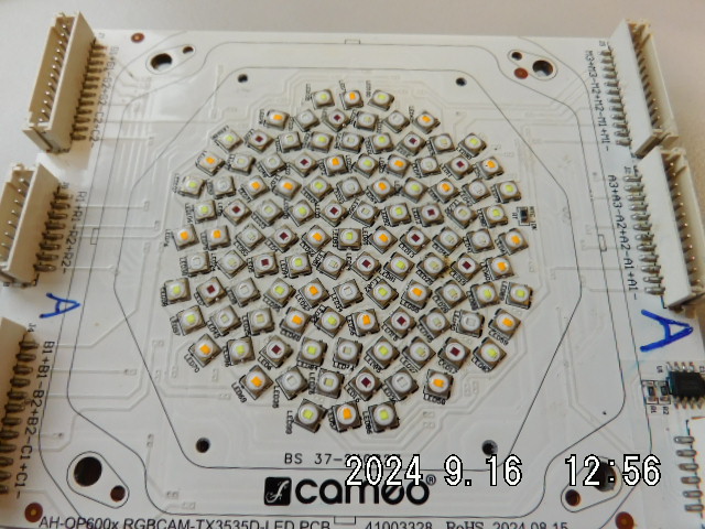
New LED arrangement for testing with different LED colours.
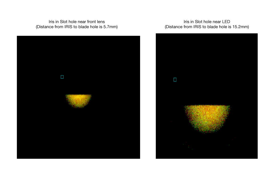
The next step is to determine the relative proportions of the different LED colours in order to achieve a well-mixed halogen white when all LEDs are driven evenly. Once the relative proportions are known, the number of LEDs can be scaled to reach the desired total luminosity – in this case, the target is that of a 2.5 kW halogen lamp Naturally, any “half” LEDs resulting from the scaling are rounded up to whole LEDs, which already suggests that the light output will exceed that of a 2.5 KW halogen profile. Further ray-tracing simulation programmes are then used to test different arrangements of the LEDs on the board before the final circuit boards are manufactured. The light beam emissions of the LED arrangement, along with the downstream optics, are simulated to generate the most colour-homogeneous light field possible. The effect of beam-shaping shutters or irises can already be taken into account in the simulation, allowing the distances of the beam-limiting inserts relative to the LED source or the optics to be determined.
Simulation with a special ray-tracing programme to compare two LED arrangements in the optical system. The calculated projection surfaces can be seen; in particular, the colour changes on the simulated beam-shaping shutters are valuable indicators.
Simulation with a special ray-tracing programme showing different distances of the iris from the LED and their effects.
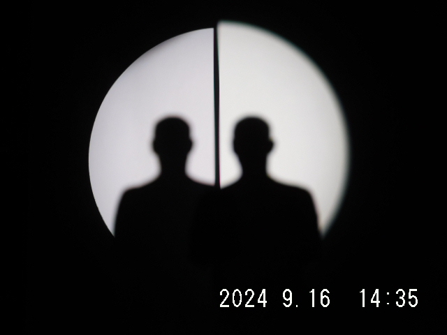
Once theory has laid the foundation for the optimal solution, reality must now demonstrate whether – and how – the various combinations and arrangements yield the best result. At this stage, an A/B comparison by eye is the ultimate measure. This is where all weaknesses become apparent and, within the limits of physics, can also be corrected.
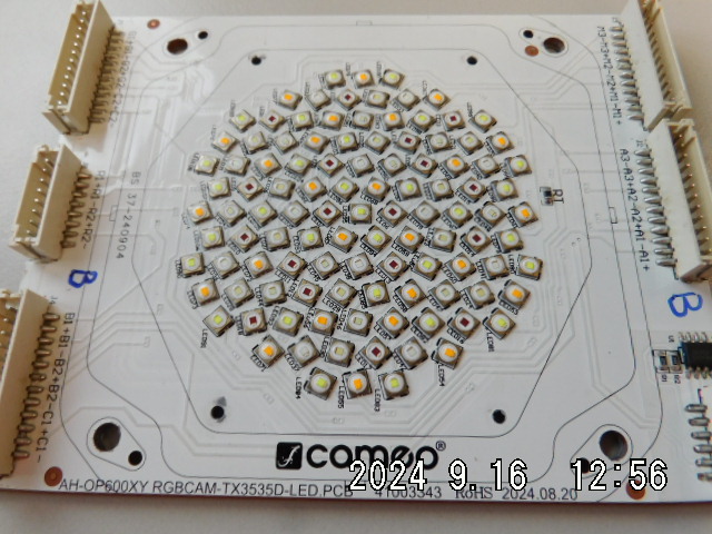
Different arrangement of the LED colours with defined positioning.
An A/B comparison by eye – better than any simulation programme or measuring device.
Once the hardware – that is, the structure of the LED light engine – has been finalised, it makes sense to build a test setup so that the firmware can be trialled in practice. For a convincing halogen simulation, the functions “response time” and “dim to warm” are generally used. “Response time” refers to the visible glow when switching on or off – mimicking the delay caused by the tungsten filament of a halogen lamp heating up or cooling down. On the P6, this can be switched to emulate a 1, 2, or 5 kW lamp, since the filament mass of a 5 kW lamp is much more sluggish than that of a 1 kW filament. This means that the P6 can be optimally adapted to existing fixtures. By contrast, “dim to warm” describes the shift of the colour temperature towards red as a halogen lamp is run at less than full power. However, to achieve a perfect halogen simulation, the dimmer curve itself also needs to be adjusted. As a rule, a lighting desk operates a leading-edge phase control dimmer for halogen lights linearly. The “dimmer-halogen light” chain results in a brightness curve that is anything but linear and behaves completely differently from an LED that is controlled linearly. This is why the dimmer curve on the P6 can be set not only in the usual linear, exponential, logarithmic, and S-curve settings, but also in a “halogen dimmer curve”.
Nicholas Heck, B.Sc., Research & Development Engineer, Light Technology, assesses the homogeneity of the light in the laboratory set-up.
Even when LEDs with very narrow binning are used, a calibration system can still extract much more from the LED setup, especially if dedicated algorithms have been developed and used to account for factors such as the influence of different temperatures or the LEDs' ageing processes. The fixtures must continue to deliver the same colour space even after later acquisitions or further production batches. Calibration also covers dimming behaviour, which ensures that the colour point does not shift when dimming – particularly when fading very slowly in or out at the lowest end of the control range. What is possible with a halogen lamp must also be achievable with the LED engine. With the P6, this needs to be theatre-grade dimming.
A calibration system in the Cameo Service in Neu-Anspach. Each fixture is calibrated again at the end of the manufacturing process. Several identically structured calibration systems are maintained for this purpose.
The algorithms embedded in the calibration unit offer two further refinements. Firstly, when using the 241 predefined LEE colour presets, it is possible to select whether the chosen filter colour appears as if lit by a halogen lamp or by a discharge lamp. The next step in control technology is the option to decide whether to achieve the greatest possible brightness in the light colour by driving the LEDs fully for colour mixing, or instead to aim for the best possible colour rendering by driving the LEDs in relation to each other so that the combined colours form as continuous a spectrum as possible.
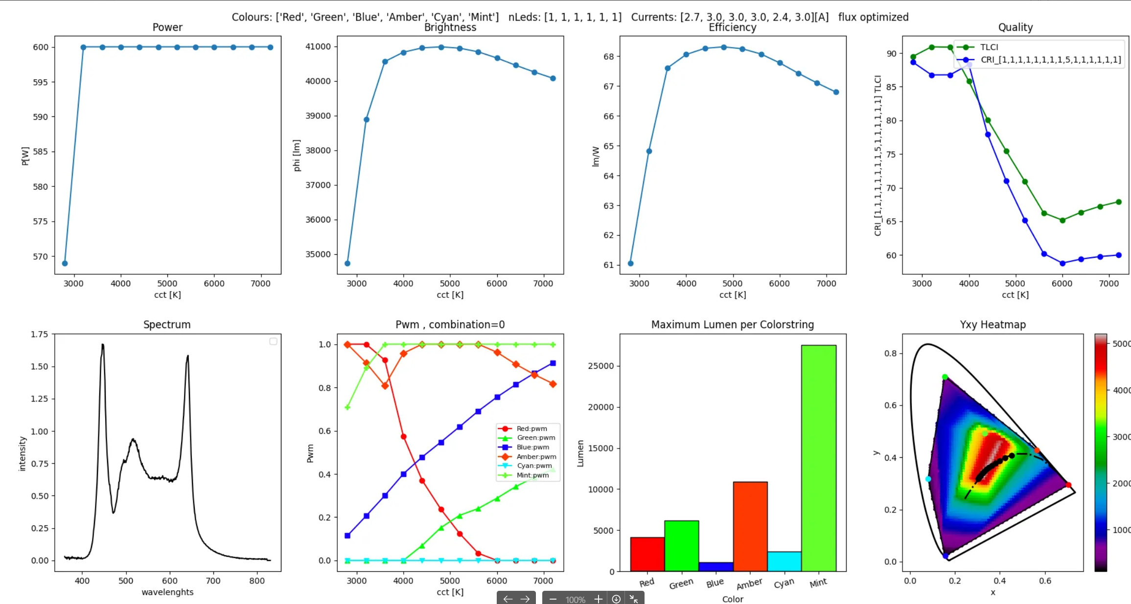
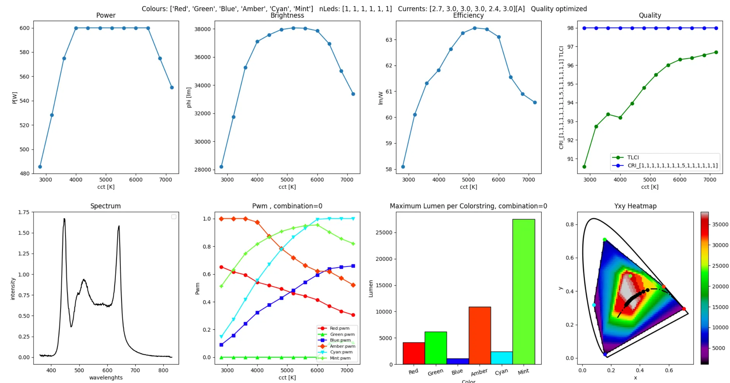
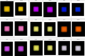
Measurement logs for optimising the various control modes for maximum colour quality or maximum light output (left: optimised brightness, right: optimised colour quality)
Several years of development work have gone into the P6 and its LED light source. It is therefore not surprising that the P6 has an Ra of 98 at a colour temperature of 5600 K and a luminous flux of 16,000 lm. And, at a halogen colour temperature of 3200 K, the R9 value even reaches an astonishing 99, all while maintaining the desired theatre-grade quality.
More information:
cameolight.com
adamhall.com